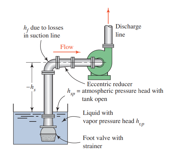
We will return to this equation after we find the losses in the system between points 1 and 2. The losses include the following: Entrance loss, friction in the 2 m of vertical pipe, minor loss in the foot valve and elbow, friction in the 1.5 m of horizontal pipe. We now compute each of these contributions. In what follows we will use the properties of liquid water at standard pressure.
Friction losses in the vertical pipe
The vertical pipe is DN 80 Schedule 40 and has an inside diameter $D=77.9~\mm$ and flow area $A=4769~\mm^2$. The velocity and velocity head are
$$ v=\frac{Q}{A}=\frac{300~\lpm}{0.004769~\m^2}\frac{\m^3/\s}{60,000~\lpm}=1.05~\m/\s \qquad\longrightarrow\qquad \frac{v^2}{2g}=0.056~\m $$ The Reynolds number and friction factor are $$ N_R=\frac{vD}{\nu}=\frac{1.05~\m/\s \times 0.0779~\m}{3.6\times 10^{-7}\m^2/\s}=2.27\times 10^{5} \qquad\longrightarrow\qquad f=0.019 $$ From Darcy's equation we find $$ h_L^{\rm DN80} = f\frac{L}{D}\left(\frac{v^2}{2g}\right)=0.019~\frac{2~\m}{0.0779~\m}(0.056~\m)=0.027~\m $$Entrance loss
We treat the entrance flow as an inward projecting pipe with resistance coefficient $K=0.78$. The entrance loss is therefore
$$ h_L^{\rm entrance}=K\left(\frac{v^2}{2g}\right)=0.78(0.056~\m)=0.044~\m $$Foot valve and elbow
The equivalent length in pipe diameters of the hinged disc type foot value is $(L_e/D)=75$ and that of the 90° long radius elbow is $(L_e/D)=20$. Since these two fittings are in the same pipe we can add their contributions and use a total $(L_e/D)=95$. The friction factor, $f_T$, is taken in the zone of complete turbulence and can be found on the schedule 40 steel pipe data table. $$ h_L^{\rm fittings}=f_T \left(\frac{L_e}{D}\right)\left(\frac{v^2}{2g}\right)=0.017(95)(0.056~\m)=0.091~\m $$
Friction losses in the horizontal pipe
The horizontal pipe is DN 50 Schedule 40 and has an inside diameter $D=52.5~\mm$ and flow area $A=2165~\mm^2$. The velocity and velocity head are
$$ v=\frac{Q}{A}=\frac{300~\lpm}{0.002165~\m^2}\frac{\m^3/\s}{60,000~\lpm}=2.31~\m/\s \qquad\longrightarrow\qquad \frac{v^2}{2g}=0.272~\m $$ The Reynolds number and friction factor are $$ N_R=\frac{vD}{\nu}=\frac{2.31~\m/\s \times 0.0525~\m}{3.6\times 10^{-7}\m^2/\s}=3.4\times 10^{5} \qquad\longrightarrow\qquad f=0.020 $$ From Darcy's equation we find $$ h_L^{\rm DN50} = f\frac{L}{D}\left(\frac{v^2}{2g}\right)=0.020~\frac{1.5~\m}{0.0525~\m}(0.271~\m)=0.155~\m $$Total losses and inlet pressure
Combining all the losses
$$ \begin{align*} h_L &= h_L^{\rm DN80} ~+~ h_L^{\rm entrance} ~+~ h_L^{\rm fittings} ~+~ h_L^{\rm DN50} \\ h_L &= 0.027~\m + 0.044~\m + 0.091~\m + 0.155~\m = 0.317~\m \end{align*} $$ We now return to our earlier derivation of the inlet pressure from the general energy equation. This was given in equation $\eqref{GEE}$ rewritten below: $$ \begin{align*} \frac{p_2}{\gamma} &= -h_L - 2~\m - \frac{v_2^2}{2g} \\ \frac{p_2}{\gamma} &= -0.317~\m - 2~\m - 0.272~\m\\ \frac{p_2}{\gamma} &= -2.59~\m~({\rm gauge}) \end{align*} $$NPSH
The Net Positive Suction Head or NPSH is the margin of pressure over the liquid's vapor pressure at the pump inlet. It is defined as the difference of the stagnation pressure, $p_s$, at the pump inlet and the vapor pressure, $p_{vp}$, of the liquid. $$ NPSH = \frac{p_s}{\gamma} - \frac{p_{vp}}{\gamma} $$ Note that we working in terms of pressure heads which is why each pressure in the above expression is divided by the specific weight of the fluid. The problem stated that that atmospheric pressure is 101.8 kPa so the atmospheric pressure head is: $$ \frac{p_{\rm atm}}{\gamma}=\frac{101.8~\kPa}{9.53~\kN/\m^2}=10.682~\m $$ I found the vapor pressure of water at 80°C to be 48.04 kPa. The vapor pressure head is therefore: $$ \frac{p_{vp}}{\gamma}= \frac{48.04~\kPa}{9.53~\kN/\m^2}=5.041~\m $$ In order to find the available NPSH we first solve for the stagnation pressure at the inlet. The stagnation pressure head is a sum of the static pressure head and velocity head $$ \frac{p_s}{\gamma}=\frac{p_2}{\gamma} + \frac{v_2^2}{2g} = -2.59~\m + 0.272 = -2.317~\m~({\rm gauge}) $$ Since the vapor pressure that appears in the formula for NPSH is expressed as an absolute pressure we must express the stagnation pressure at the inlet as an absolute pressure as well: $$ \frac{p_s}{\gamma} ({\rm abs.}) = \frac{p_s}{\gamma} ({\rm gauge}) +\frac{p_{\rm atm}}{\gamma} = -2.317~\m + 10.682~\m = 8.365~\m $$ Now we can compute the NPSH: $$ NPSH=\frac{p_s}{\gamma} ({\rm abs.}) - \frac{p_{vp}}{\gamma}=8.365~\m - 5.041~\m=3.324~\m $$